MTX 512 (debugging thread)

GozdniJezek
Posts: 32
Joined: 07 Jun 2019 20:49

Re: MTX 512 (debugging thread)

Post by GozdniJezek »

Hello,
all of the measurements were done with disconnected keyboard.
Immediately after turning the machine on the values are:
voltage across R16: 0.003 V
Pin1 and GND on 9C (4070B): 4.873 V
across C11: 4.912 V

I presume everything looks as expected and this matches the symptoms (stable picture for couple of seconds).
However after some time when the picture gets lost the values are:
voltage across R16: 0.218 V
Pin1 and GND on 9C (4070B): 3.5 V
across C11: 3.0 V

If I understand correctly than the issue could be either C11 (voltage is lower than on 9C) or there is a unwanted connection.
But the symptoms are the same like they were before I changed out C11 with a new one, would it be fair to say that lowers the chances of two bad capacitors in a row :). I'll check for any shorts around this circuitry, however the couple of seconds of working order before going bad, sounds like 9C is more likely culprit, does that sound reasonable?

Thank you for your help.
User avatar
1024MAK
Posts: 757
Joined: 24 Dec 2012 03:01
Location: Looking forward to summer, in Somerset, UK

Re: MTX 512 (debugging thread)

Post by 1024MAK »

That’s very strange! So at power on, C11 is charging up (normal and too fast to see with a meter) and then slowly being discharged, and at a rate faster than R18 can recharge it.

If C11 has already been changed, it’s unlikely but still possible that the replacement is faulty.

Given the small voltage across R16, I don’t think the chip (9C) is the problem. If the chip was faulty and discharging C11, the voltage across R16 would be much higher.

So the next thing to look at is resistor R18. When the symptom is present, do you have a nice steady +5V supply voltage at one end? What voltage do you get at the other lead? Is this similar to the voltage across C11?

Do you have a spare resistor, preferably a 10k resistor, but any value between 1k and 22k will do. Find a different +5V supply point to the +5V supply feeding R18 (any +5V supply point will do, for example pins 12, 13 or 14 of 9C logic gate), and connect this to your spare resistor with a wire. Then connect the other end of the resistor to pin 1 on 9C logic gate (4070B). Do confirm with your meter that the +5V supply point you use is actually at +5V.

Measure the voltages as before (across C11, R16 and pin 1 of IC 9C (fiddly I know).

Mark
:!: Standby alert :!:
“There are four lights!”
Step up to red alert. Sir, are you absolutely sure? It does mean changing the bulb :!:
Looking forward to summer in Somerset later in the year :D

Not as many MTXs as Dave! :lol:
stephen_usher
Posts: 325
Joined: 27 Nov 2016 19:58

Re: MTX 512 (debugging thread)

Post by stephen_usher »

If you've got a multimeter which can measure current, pull the fuse and clip the multimeter between the two sockets and see how much the machine is drawing. It should be pulling about 0.85 amps. Anything significantly more than that and something is taking too much.
GozdniJezek
Posts: 32
Joined: 07 Jun 2019 20:49

Re: MTX 512 (debugging thread)

Post by GozdniJezek »

Hello, time for a new report. :)

My friend removed the C11 and measured it with a tester and multimeter and he got:
tester:
C11 ( 10uF 50V electrolyte)
10.68 uF
ESR 1.1 Ohm,
Vloss 1.4

Multimeter:
10.03 uF

Judging by the measurements this should also be OK.
1.JPG
1.JPG (77.27 KiB) Viewed 13065 times
0.793A measured across the fuse. I think this is in spec.
The yellow channel is the voltage on C11, the blue is the output from 4070B (both values correspond to the 5V, they are just offset). All was measured without the keyboard.

The voltage on R18 is a stable 5V.

But he changed the C11 nevertheless for another brand new one and this resulted in stable reset (yaay :D) (for now at least :D ) , so Mark was spot on once again! :) (thank you Mark)
The new C11 is 10 uF 25V, ESR 1.5 Ohm

Now the image was stable for at least 20 minutes as far as he tested.
2.JPG
2.JPG (73.27 KiB) Viewed 13065 times
Now this looks like another bad 4116, which I can handle as they are all socked now. :) (the image is black and white, because we've changed the link on the video board to B (bypassing the mixing chip) during the testing. Does this sound reasonable? As we've tested all of the video ram connections for continuity and for shorts.

Any thoughts? Was it all because of a possibly weird C11? He did report, that he got a stable picture with the old C11 after he soldered wires to it for measurement (it's possible that he fixed a cold join with this? Or changed some properties of C11 with scope probes attached to it?), but after manually resetting on the keyboard connection circuit exempted the old symptoms again. He doesn't want to try the reset again with the new capacitor :D so this is it for now :)

Any other ideas and suggestions? :)


As always thank you for your help.
GozdniJezek
Posts: 32
Joined: 07 Jun 2019 20:49

Re: MTX 512 (debugging thread)

Post by GozdniJezek »

Hello, I think I'm due for an update, sorry for such delay, but better late than never. :)
To recap what has been done:

-One of video RAM chips (4116) was bad and it was replaced

-C11 was replaced but had a cold solder joint, symptoms: after a while the computer went into a "reset loop", on screen the signal (video output) could be seen for a fraction of a second. Resolution: fixed the cold joint on C11

-After the reset issue was fixed the image was "stable/persistent", however after a couple of seconds the image got weird artefacts (see Image) covering the whole screen.
IMG_20210328_111430.jpg
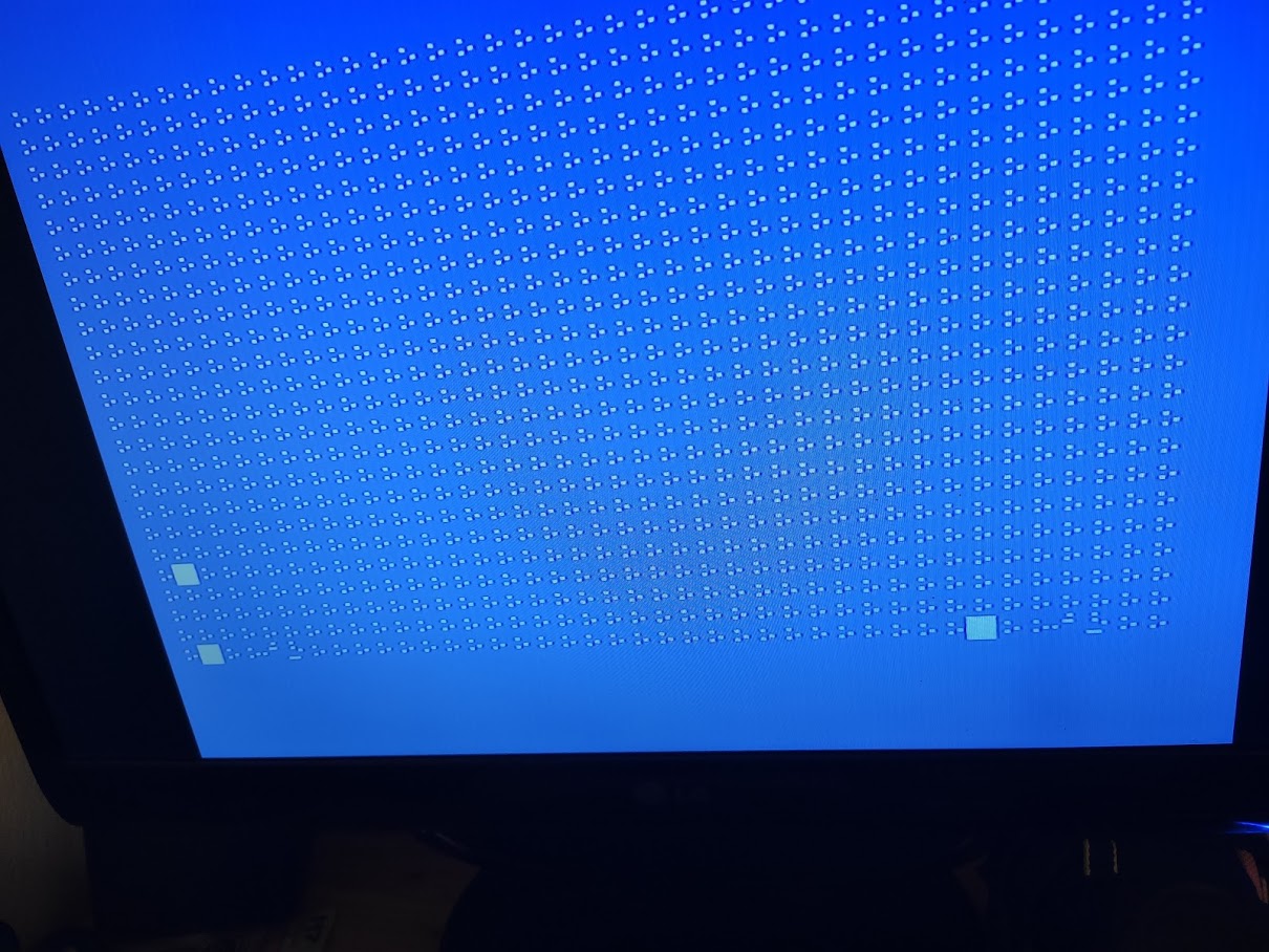
IMG_20210328_111430.jpg (264.37 KiB) Viewed 11578 times

-At this stage I wanted to see what happened if I run a Basic program (simple print loop), however trying to type it in I noticed that some of the keys were dead. I checked the continuity on keyboard and connected logic etc.... Checking the keyboard matrix I noticed that all of the nonworking letters were on the same line, this lead me to changing the 74LS273 at 3A, which fixed the dead letters and allowed me to type in a print loop. I left the loop running for 1h and the screen was fine (without artefacts) this lead me to believe the computer was generally working and that the artefacts are caused by the input part and the video RAM/display part was fine.

At this stage I swapped the 74LS244 at D1, C1 and E2 this gave me a stable basic prompt. (I only recently got TL866II Plus that will enable me to test which chip was faulty) I was dealing with fake Chinese LS244 in between that's why I swapped all 3 of them and I was a bit desperate :D . Interchanging 74xx244 between sockets, produced similar image, just the pattern was a bit different (hopefully someone will find this information useful).

At this point I switched the Link 6 and link 7 to 512 configuration, but the computer at this stage booted to black screen, after some inspection of the PAL14L4 extension board (timing fixing board) I noticed a cold solder joint on one of the pins. After a fix the computer boots to basic.
IMG_20210605_142522.jpg
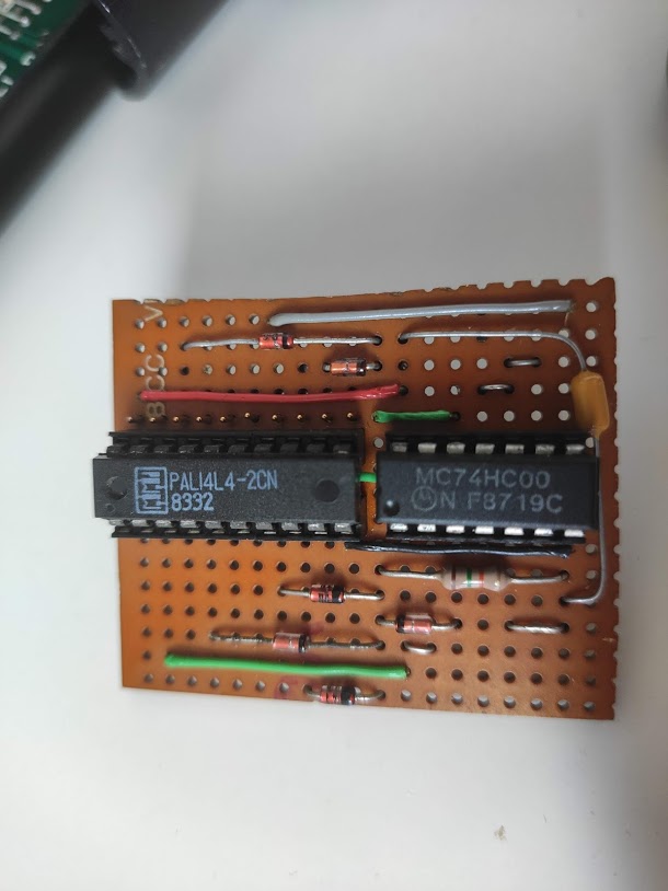
IMG_20210605_142522.jpg (65.05 KiB) Viewed 11578 times
I had some issues loading software (because of using stereo cable, stupid I know :) 
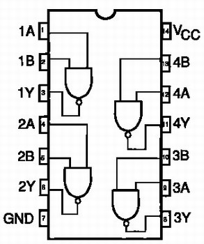
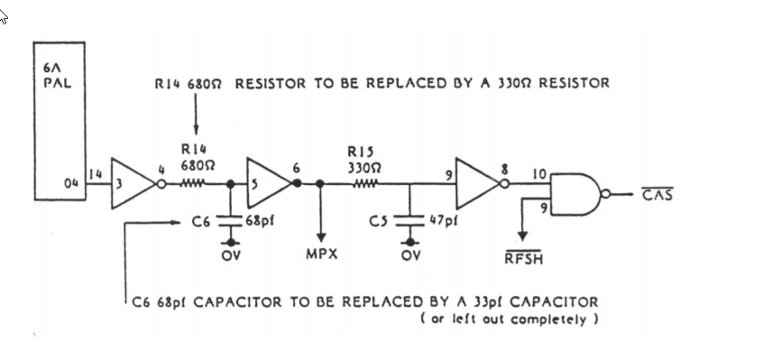
) which led me to study the timing correction board a bit. The result is the attached schema of it. It's basically an logical AND operation (over multiple NAND gates, 74HC00 logic chip) between pin 14 on PAL14L4 chip and pin 2, 4, 7 and 18. I checked the continuity of the board but all was fine, then I realized the cable I was using was stereo :) .
MTX_timing_board.pdf
(59.76 KiB) Downloaded 441 times
Ext-2201-000.jpg
Ext-2201-000.jpg (26.48 KiB) Viewed 11578 times
unnamed.png
unnamed.png (88.69 KiB) Viewed 11578 times
After making a mono cable everything seems to work fine and I'm very happy to save this wonderful part of computer history.

It was an epic struggle (mainly because the Chinese poste, COVID delays and my learning process), but worth it and I really appreciate all of the help and feedback from the wonderful community.


Have a nice day and thanks for all the help.
GozdniJezek
Posts: 32
Joined: 07 Jun 2019 20:49

Re: MTX 512 (debugging thread)

Post by GozdniJezek »

victory.png
victory.png (2.08 MiB) Viewed 11578 times

I've also played this wonderful homebrew (I someone has links to other homebrew software I would be very grateful). I've checked the software topic on this forum, the resources on: http://www.primrosebank.net/computers/m ... are_dl.htm and mtxworld.

Does anyone have a compilation of waw files? I'm aware of the one on mtxworld but I'm wondering if anyone has anything newer?
Martin A
Posts: 797
Joined: 09 Nov 2013 21:03

Re: MTX 512 (debugging thread)

Post by Martin A »

All the "new" games I'm aware of are already on Dave's download page. However, I think the newer ones are all .RUN files aimed at MEMU or "disc" systems.

Unfortunately thers' no straightforward way to convert a .RUN to WAV files to load from BASIC. That's because support for .RUN files only exists in the SDX/FDX extensions to to BASIC.

If Magrom or CFX doesn't appeal, you could try the DIY "disc" system route to making more software available viewtopic.php?p=2619#p2619
GozdniJezek
Posts: 32
Joined: 07 Jun 2019 20:49

Re: MTX 512 (debugging thread)

Post by GozdniJezek »

Yes I noticed, that waw is not popular anymore. I'll explore the hardware, you suggested, but for starters I believe I'll just go with mp3 player. Is it possible to get preassembled Magrom or CFX or is it all DIY? :) (latest info: Current Stock : 19/06/2020 for MAGROM) Thank you for your help.
User avatar
1024MAK
Posts: 757
Joined: 24 Dec 2012 03:01
Location: Looking forward to summer, in Somerset, UK

Re: MTX 512 (debugging thread)

Post by 1024MAK »

Well done on getting your MTX fully working :D 8-)

Nice to see that you are enjoying using it :lol:

Mark
:!: Standby alert :!:
“There are four lights!”
Step up to red alert. Sir, are you absolutely sure? It does mean changing the bulb :!:
Looking forward to summer in Somerset later in the year :D

Not as many MTXs as Dave! :lol:
User avatar
Dave
Posts: 1278
Joined: 11 Aug 2012 18:16
Contact:

Re: MTX 512 (debugging thread)

Post by Dave »

GozdniJezek wrote: 30 Jun 2021 17:42 Yes I noticed, that waw is not popular anymore. I'll explore the hardware, you suggested, but for starters I believe I'll just go with mp3 player. Is it possible to get preassembled Magrom or CFX or is it all DIY? :) (latest info: Current Stock : 19/06/2020 for MAGROM) Thank you for your help.
The option IS preassembled
See the bottom of this page for MAGROM http://www.primrosebank.net/computers/ ... orders.htm

And here for CFX http://www.primrosebank.net/computers/ ... ailability
Post Reply