Page 12 of 23
Re: Resurrecting an MTX500.
Posted: 10 May 2019 23:37
by stephen_usher
Martin A wrote: ↑10 May 2019 23:09
stephen_usher wrote: ↑10 May 2019 20:16
I'm home now. I've programmed a GAL with the 3 ROM & 64K RAM JEB file from Andy's site, fitted it and the ROM select line is still constantly high.
The address lines are active as is the _RD line but no ROM select.
What's the logic used to generate the ROM select for ROM A? Maybe I'm missing something.
The 3 rom 4000-05 MTX is only covered in the original manual, it looks like /CEA is the chip select for the A rom, and /CE64B is B and C rom select that goes to 10J to be separated.
Indeed, and neither /CEA nor /CE64B ever go low.
The three address lines are very active as are /MREQ and /RD. R0, R1 and R3 are all low.
Re: Resurrecting an MTX500.
Posted: 10 May 2019 23:48
by 1024MAK
What is the state of the other inputs to the GAL/PAL (6A)?
Mark
Re: Resurrecting an MTX500.
Posted: 11 May 2019 00:16
by stephen_usher
- 1 (A13) Busy, square waves
- 2 (A14) Busy, square waves
- 3 (A15) Busy, square waves
- 4 (P2) Low
- 5 (R1) Low
- 6 (R2) Low
- 7 (P1) Low
- 8 (/MREQ) Busy narrow square waves
- 9 (/RD) Busy, narrow square waves
- 10 (GRND) 0v
- 11 (?) High
- 12 (?) Low
- 13 (/RE-CPM) High
- 14 (->/CAS) Busy, narrow square waves
- 15 (NA15) Single square pulse, 180 per second.
- 16 (-> /GROM and /CE68B) High
- 17 (/CEA) High
- 18 (P3) Low
- 19 (R0) Low
- 20 (VCC) +5V
Re: Resurrecting an MTX500.
Posted: 11 May 2019 00:23
by Dave
If Pin 13 is constantly high, the ROMs can never be enabled.
It’s controlled by the Page Port (0)
(The pin name means ROM enabled when low, CPM [RAM mode] when high)
Re: Resurrecting an MTX500.
Posted: 11 May 2019 00:52
by 1024MAK
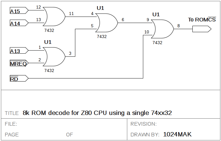
8k ROM decode for Z80 CPU using a single 74xx32
- 8k ROM decode for Z80 CPU using a single 74xx32
- 8k ROM decode for Z80 CPU using a single 74xx32.png (34.68 KiB) Viewed 6524 times
While you were taking measurements, I drew this in case it helps. It only decodes the one 8k ROM. So use it in addition to the GAL/PAL and replace the ROM CS with the output of this circuit (use a test ROM, not the MTX OS/BASIC ROMs). You can remove the GAL/PAL and use only this circuit, but then no RAM will be enabled [be sure to tie the DRAM control line to the inactive state, e.g. ground IC 2B (74LS14) pin 5]. More details
here 
But you do need to investigate the /RE-CPM control line. This comes from IC 5A (74LS273) pin 9. Check that pin 1 receives a low reset pulse when the computer is reset. After reset, all the outputs of IC 5A (74LS273) should be low.
Mark
Re: Resurrecting an MTX500.
Posted: 11 May 2019 01:10
by stephen_usher
Dave wrote: ↑11 May 2019 00:23
If Pin 13 is constantly high, the ROMs can never be enabled.
It’s controlled by the Page Port (0)
(The pin name means ROM enabled when low, CPM [RAM mode] when high)
Ah. OK, so maybe it's the 74LS273 then. Only of the very few chips I've (a) not replaced and, (b) not got in stock. Time for an order to Farnell and hope that they don't mis-pick as they did for the CD4013Bs I ordered to fix the PAL board. (In the bag marked CD4013B there were 74HC14Ns. :-/)
Re: Resurrecting an MTX500.
Posted: 11 May 2019 01:43
by 1024MAK
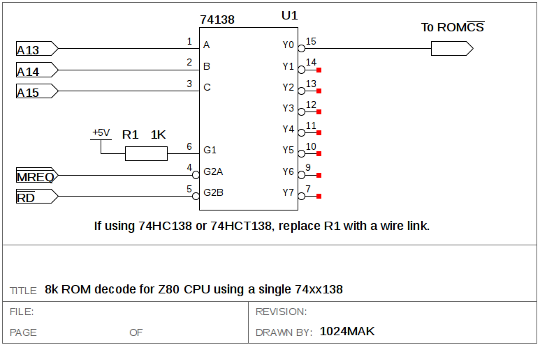
8k ROM decode for Z80 CPU using a single 74xx138
- 8k ROM decode for Z80 CPU using a single 74xx138
- 8k ROM decode for Z80 CPU using a single 74xx138.png (37.21 KiB) Viewed 6518 times
Mark
Re: Resurrecting an MTX500.
Posted: 11 May 2019 01:52
by stephen_usher
It definitely looks like it's a problem with 5A as the input to the flip-flop is going up and down nicely.
With the PAL in circuit the line is floating, which is probably why I was getting intermittent ROM selects randomly. The GAL pulls the line high.
If I bridge pins 8 and 9 on 5A I get ROM select pulses.
In other news, the PAL board seems to have stopped working entirely now. It was working poorly, as before earlier in the evening after I changed a transistor. Using the 'scope I think it might well be the 1889 that's gone for a Burton. That should arrive from Retroleum on Monday, Royal Mail allowing. In the meantime I've ordered the LS273 replacement.
Re: Resurrecting an MTX500.
Posted: 11 May 2019 02:13
by 1024MAK
With the PAL video board, if using the baseband / composite video output, you can by-pass the LM1889 by removing link 'a' and fitting link 'b'. You should then get a monochrome video output.
Note that C52 is deleted and replaced with C63, 100uF 16V or 25V (I recommend 25V).
Note that C51 is deleted and replaced with C62, 10uF 16V or 25V (I recommend 25V or greater), positive to Q6 base.
If using the RF/UHF TV output, note that the modulator obtains its +5V via R47 (470R) and ZD4 (5.1V zener diode).
Mark
Re: Resurrecting an MTX500.
Posted: 11 May 2019 09:23
by Martin A
You can also feed the Y output from J12 pin 2 to a composite monitor or SCART TV. The signal needs to go through a resistor to form a voltage divider as the 9929 outputs a nominal 3v peak voltage, and composite 1v (on SCART at least)
470R is the resistor value I found "on the net". That to me seems a bit on the high side. If the load for the monitor or TV is 150R that reduces a 3v signal to 0.73 peak to peak. Which is fine, but SCART is set up for 75R. IF that's the case then I would be thinking to use 220R instead of 470R.
Mark, this is more your field than mine, any comments ?