No picture.

About original Memotech hardware.
User avatar
1024MAK
Posts: 757
Joined: 24 Dec 2012 03:01
Location: Looking forward to summer, in Somerset, UK

Re: No picture.

Post by 1024MAK »

Steven.G wrote: 20 Jul 2020 23:10 6.15 on C51 and 0.61 on C56.

Steve..
Both those are very low compared to what they should be :(

Mark
:!: Standby alert :!:
“There are four lights!”
Step up to red alert. Sir, are you absolutely sure? It does mean changing the bulb :!:
Looking forward to summer in Somerset later in the year :D

Not as many MTXs as Dave! :lol:
User avatar
1024MAK
Posts: 757
Joined: 24 Dec 2012 03:01
Location: Looking forward to summer, in Somerset, UK

Re: No picture.

Post by 1024MAK »

Can you remove the fuse from the MTX main board and then test again on C51 and C56 please.

Mark
:!: Standby alert :!:
“There are four lights!”
Step up to red alert. Sir, are you absolutely sure? It does mean changing the bulb :!:
Looking forward to summer in Somerset later in the year :D

Not as many MTXs as Dave! :lol:
User avatar
1024MAK
Posts: 757
Joined: 24 Dec 2012 03:01
Location: Looking forward to summer, in Somerset, UK

Re: No picture.

Post by 1024MAK »

Also test across capacitor C53 (between the video board, the fuse and the internal edge-connector.

Mark
:!: Standby alert :!:
“There are four lights!”
Step up to red alert. Sir, are you absolutely sure? It does mean changing the bulb :!:
Looking forward to summer in Somerset later in the year :D

Not as many MTXs as Dave! :lol:
Steven.G
Posts: 45
Joined: 18 Jul 2020 14:03

Re: No picture.

Post by Steven.G »

6.19 on C51 and 1.2 on C56.
Steven.G
Posts: 45
Joined: 18 Jul 2020 14:03

Re: No picture.

Post by Steven.G »

C53 = 35.6, with and without fuse.
User avatar
1024MAK
Posts: 757
Joined: 24 Dec 2012 03:01
Location: Looking forward to summer, in Somerset, UK

Re: No picture.

Post by 1024MAK »

That’s definitely not good. C53 should not be more than 15V.

I’ll have to have a think about this...

Mark
:!: Standby alert :!:
“There are four lights!”
Step up to red alert. Sir, are you absolutely sure? It does mean changing the bulb :!:
Looking forward to summer in Somerset later in the year :D

Not as many MTXs as Dave! :lol:
Steven.G
Posts: 45
Joined: 18 Jul 2020 14:03

Re: No picture.

Post by Steven.G »

I checked again in case I made a mistake but no, I had to set the meter to 200 as it displayed overload at 20.

Steve..
User avatar
1024MAK
Posts: 757
Joined: 24 Dec 2012 03:01
Location: Looking forward to summer, in Somerset, UK

Re: No picture.

Post by 1024MAK »

All the following tests are to be done with the PSU and computer disconnected from the mains supply.

Switch your multimeter to the 200 ohms resistance range. Test this is working by touching the probes together, the meter should indicate around zero ohms or just above (0.1 to 0.9 depending on the resistance of the leads and how clean the probe tips are). Take a note of this value.

Now test between the negative lead of capacitor C56 (left hand lead, next to the modulator) and the negative lead of capacitor C51 (marked with a white or black stripe, lead nearest the DIN power socket).

Next test between the negative lead of capacitor C56 (left hand lead) and the negative lead of capacitor C53 (marked with a black stripe, left hand lead).

For the next tests, you will need a either a spare 6 pin DIN plug of a piece of suitable solid core wire. The diameter of the wire should be the same as or less than the diameter of a pin on the DIN plug. The most common thin solid core wire is that used for fixed telephone or ethernet cable, an off-cut of some scrap wire with 5he insulation stripped off the ends will do.

If you have croc clips, these make these tests much easier.

Connect one meter lead/probe/croc clip to the negative lead of C56. Connect the other meter lead/probe/croc clip to your piece of wire or to the appropriate pin on your spare DIN plug.

Now test to pin 3 on the DIN socket. Repeat using pin 4. See the photos below:
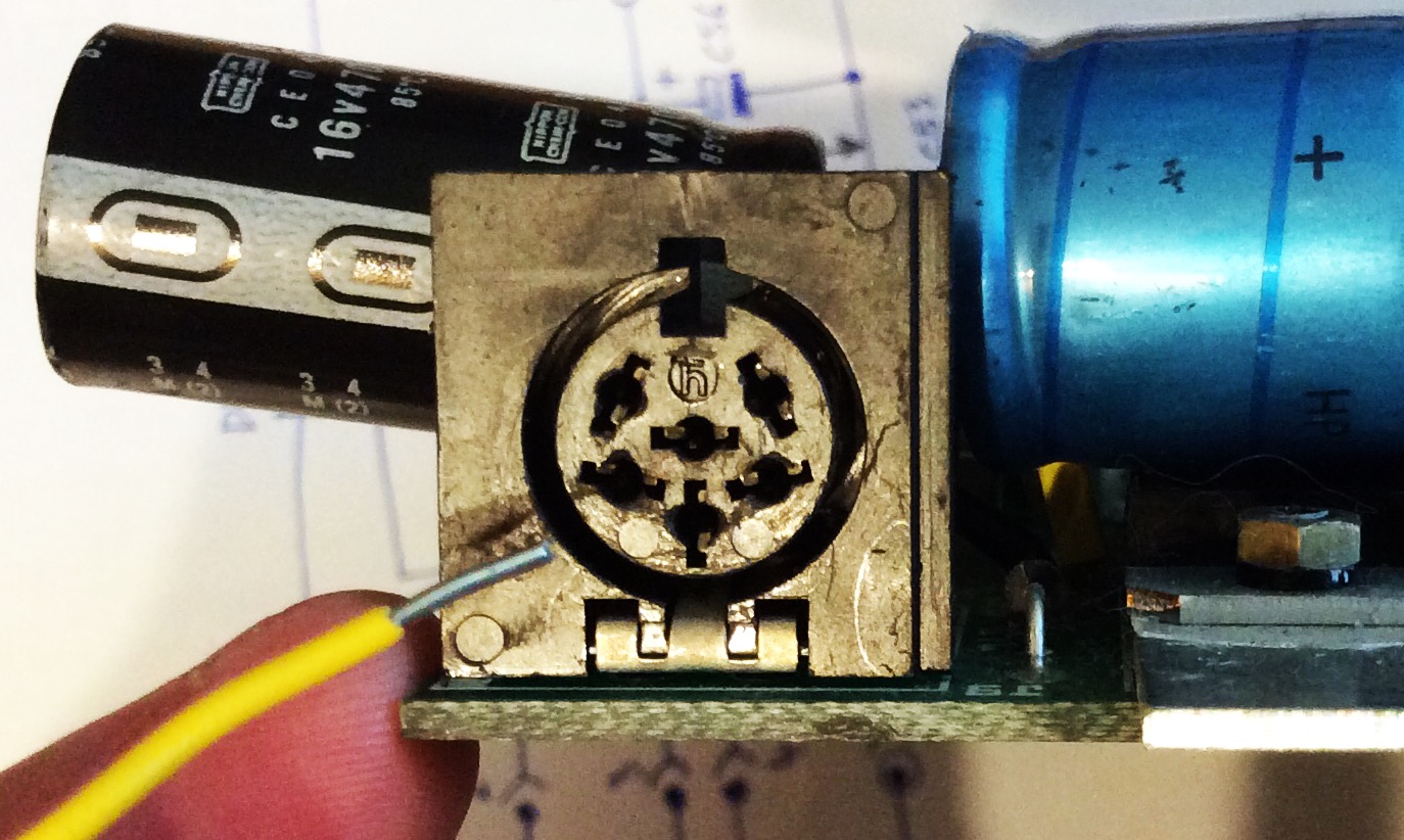
6 pin DIN socket and test wire
900267A6-90A8-41D8-A00A-FDFBEC82BEBD.jpeg (292.72 KiB) Viewed 7042 times
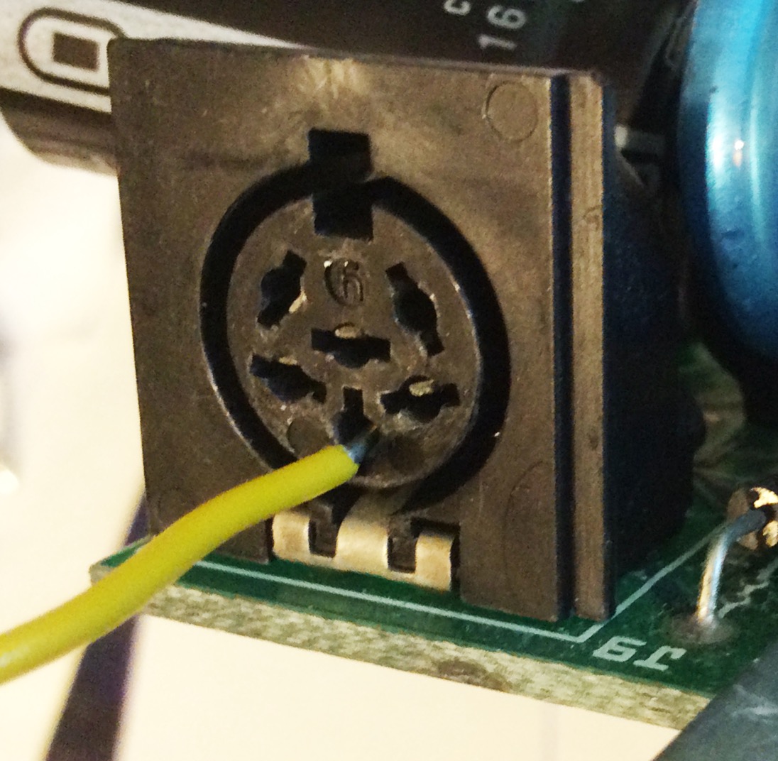
Pin 3
Pin 3
39AF5008-5632-41F7-8CE8-C310837C9F79.jpeg (250.22 KiB) Viewed 7042 times
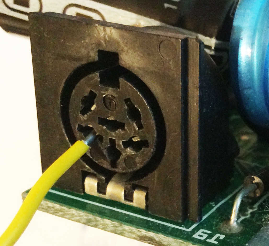
Pin 4
Pin 4
5F244B11-F1D6-4632-B9DE-6CE950A95420.jpeg (230.03 KiB) Viewed 7042 times
The objective of the above tests was to test the continuity of the 0V/GND ground network on the PCB.

Mark
:!: Standby alert :!:
“There are four lights!”
Step up to red alert. Sir, are you absolutely sure? It does mean changing the bulb :!:
Looking forward to summer in Somerset later in the year :D

Not as many MTXs as Dave! :lol:
Steven.G
Posts: 45
Joined: 18 Jul 2020 14:03

Re: No picture.

Post by Steven.G »

Triple checked, all readings were zero.

Steve..
User avatar
1024MAK
Posts: 757
Joined: 24 Dec 2012 03:01
Location: Looking forward to summer, in Somerset, UK

Re: No picture.

Post by 1024MAK »

Okay, still with the power off, and still with the multimeter set to the 200 ohm resistance range. Now test between the following pins of the PSU DIN plug:

1 to 2

2 to 3

3 to 4

4 to 5

Report back your results.

Does your multimeter have a diode test range?

Mark
:!: Standby alert :!:
“There are four lights!”
Step up to red alert. Sir, are you absolutely sure? It does mean changing the bulb :!:
Looking forward to summer in Somerset later in the year :D

Not as many MTXs as Dave! :lol:
Post Reply