Page 6 of 10
Re: No picture.
Posted: 22 Jul 2020 21:45
by Dave
If you redo tests, I'm pretty sure you'll find that they are not all connected.
Try remeasuring the resistance before you disconnect
Re: No picture.
Posted: 22 Jul 2020 23:00
by 1024MAK
Steven.G wrote: ↑22 Jul 2020 21:26
BTW the fuse is a T1.6a, and why would you put a fuse inside a sealed case???
Also I was thinking when testing the tabs in the PSU the reading is always going to be false if as it seems 1,2 &4 are connected!
Would it be a good idea to disconnect the wires then test?
It’s rather common to put fuses in places where the user / consumer can’t get at them. Then slap a warning on the outside: “no user serviceable parts inside”. Sometimes these fuses are soldered onto the board (yes, fuses with lead out wires for use on PCBs exist, including surface mounting types).
Although the secondary coil windings of transformers will have a low resistance, they may show as anything from fractions of an ohm to five to ten ohms on a multimeter depending on the size of the wire used and the number of turns of wire used.
I can’t remember what the MTX PSU are normally (without testing one of mine). But they maybe in the ball park of 0.3 to 1 ohms (but don’t quote me on that)...
No need to disconnect yet. Let us see your numbers first.
Mark
Re: No picture.
Posted: 23 Jul 2020 00:39
by Dave
1024MAK wrote: ↑22 Jul 2020 23:00
they maybe in the ball park of 0.3 to 1 ohms
Total end to end resistance is ~1.7 ohms on one of mine

Re: No picture.
Posted: 23 Jul 2020 16:44
by Steven.G
I retested the PSU tabs and got these reading,
blue to green gives 0.4 ohms
green to white gives 0.6 ohms
white to orange gives 0.6 ohms
I also retested blue to the din pins and took pics so you can see pins 1,2 and 5 seem to be connected.
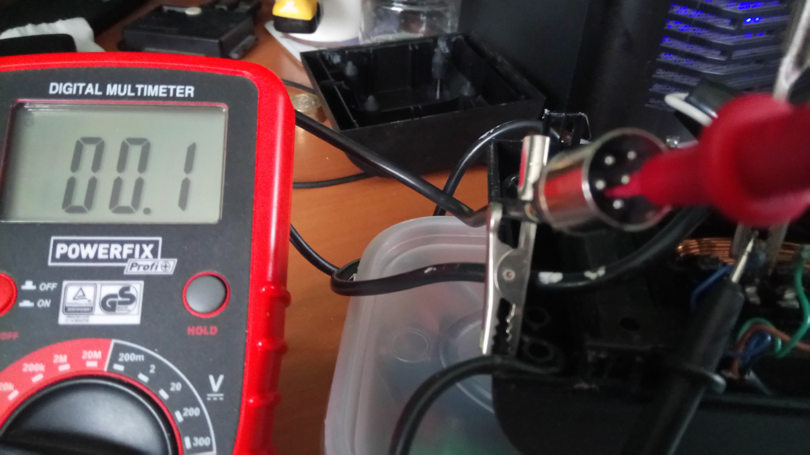
- Pin 1 to blue.
- Pin1.JPG (449.3 KiB) Viewed 7195 times
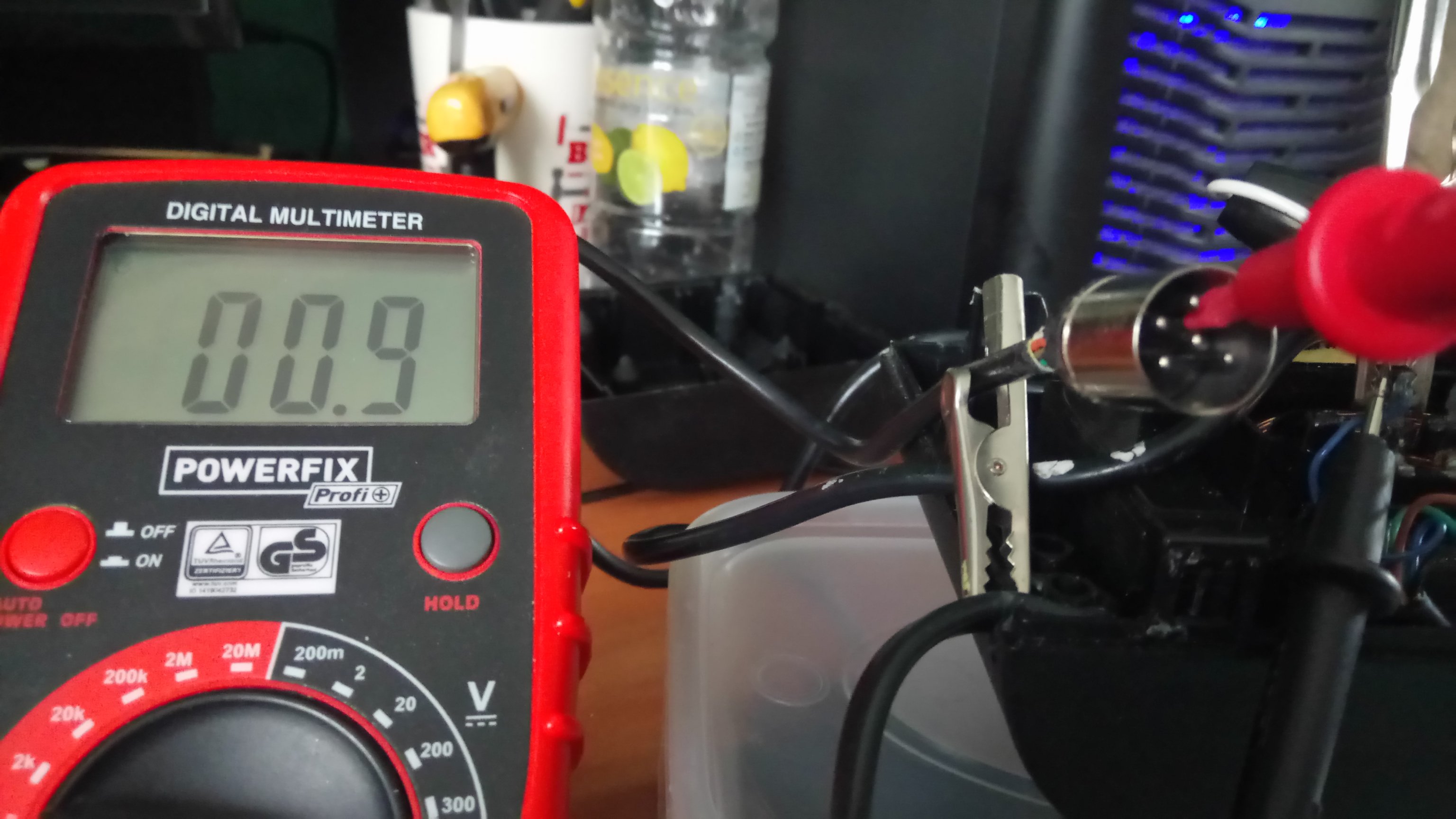
- Pin 2 to blue.
- Pin 2.JPG (426.15 KiB) Viewed 7195 times
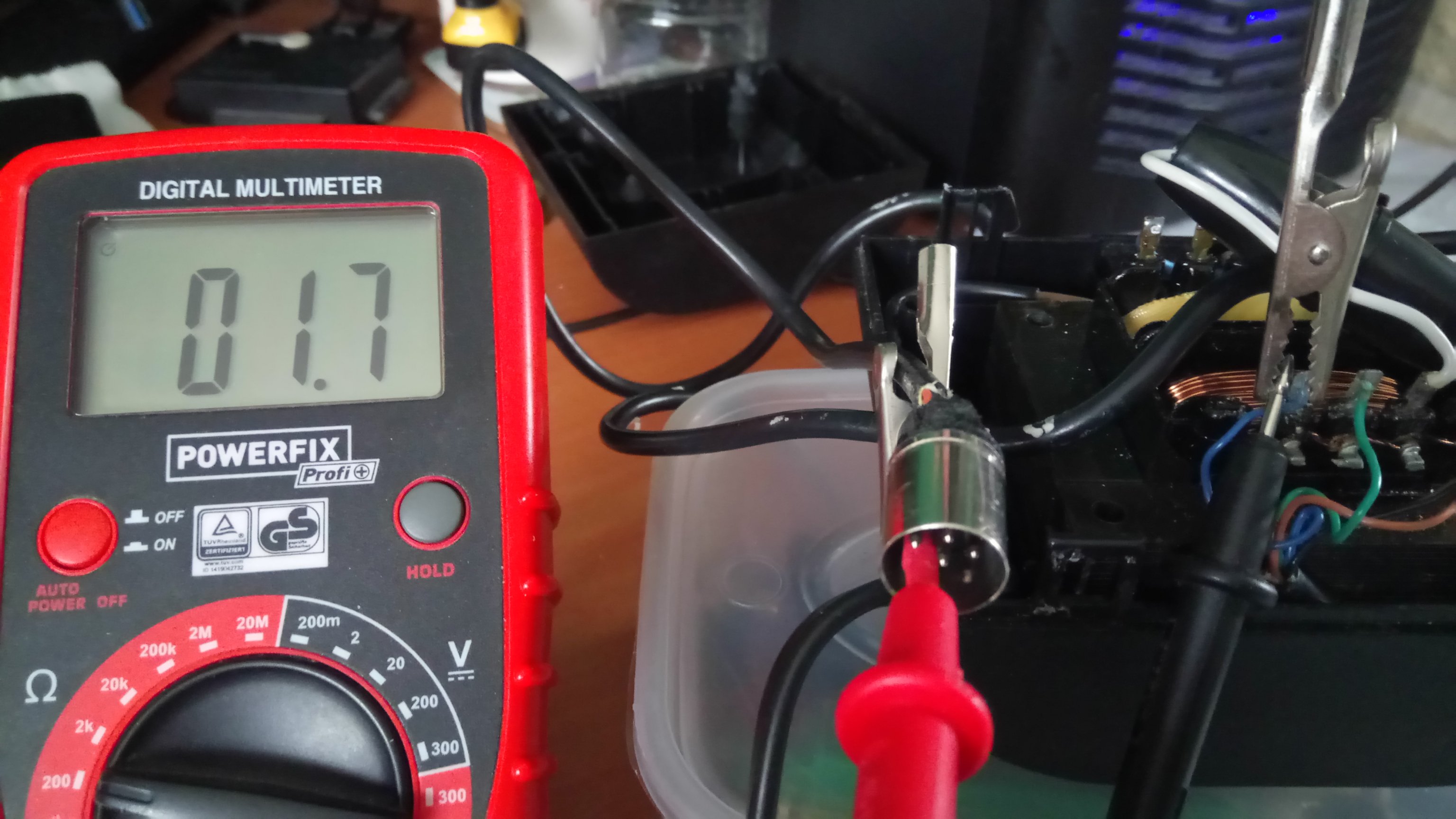
- Pin 5 to blue.
- Pin5.JPG (468.78 KiB) Viewed 7195 times
I've ordered a new din plug so I think I might wrap the cable and plug to protect them and see if I can melt the plastic enough to remove it.
Steve..
Re: No picture.
Posted: 23 Jul 2020 17:14
by Dave
- mtxpsu1.gif (3.49 KiB) Viewed 7194 times
This might help
Yes, 1, 2 and 5 are connected - through the coils, with resistance increasing as you include coils, i.e., R1-5 > R1-3/4 > R1-2
As I said, one of mine has an end-to-end (R1-5) resistance of 1.7 ohms too
Looking at the diagram, you can see how the (low, but measurable) resistances might be expected to increase.
Pin 5 to Pins 3/4 develop 9V under power (ends up as the negative supply in the MTX)
Pin 2 to Pins 3/4 also develops 9V under power (ends up as the positive supply in the MTX)
The two coils have similar resistances
Pin 1 to Pin 2 effectively gives 4.5V under power - and can be expected to be half the resistance of the other two coils
Re: No picture.
Posted: 23 Jul 2020 17:24
by Steven.G
So should I just forget about the old DIN plug and replace it add a new fuse and see where I'm at then??
Steve..
Re: No picture.
Posted: 23 Jul 2020 17:27
by Dave
Yes, but You can probably even just replace the fuse (with a nail - JOKE!) and see what happens
Obviously, but I'll say it anyway - remove your test wires and either put the cover back on, or keep well away from it, while you power it on !
Re: No picture.
Posted: 23 Jul 2020 19:17
by 1024MAK
Due to the design of the circuitry inside the MTX computer, I’m not happy with that fuse arrangement. Rather than providing protection, it severely affects the voltages inside the computer has has unintended consequences for the negative supply rail.
Do you have. 40W or 60W conventional tungsten filament lamp, suitable lamp holder, 13A plug, 3A two or three core flex and a suitable mains connection block or 13A socket outlet?
Mark
Re: No picture.
Posted: 23 Jul 2020 20:15
by Steven.G
I don't have any 1.6a fuses so just ordered some, will have to wait until they arrive for future testing.
_________
40W or 60W conventional tungsten filament lamp - only have a 100w bulb
suitable lamp holder, check
13A plug, check
3A, ????
two or three core flex, check
suitable mains connection block or 13A socket outlet, check
So basically I have a 100w inspection lamp.
Steve..
Re: No picture.
Posted: 23 Jul 2020 21:19
by 1024MAK
A method of testing that limits the fault current is to use a normal light bulb (I recommend a 40W or 60W, you can try a 100W at your own risk, whatever the wattage it MUST be a filament type only). Beware that this will be at mains voltage. Connect up as per the diagram below:-

This circuit limits the amount of power that the unit can draw from the mains, therefore if there is a fault or problem with the PSU the lamp will glow brightly and the current will be limited. There is less likelihood that the unit will suffer further damage.
Now, with a lamp in circuit, it is likely that the computer may not work correctly.
Good luck
 Mark
Mark