Page 8 of 10
Re: No picture.
Posted: 28 Jul 2020 12:20
by Dave
Just that you'd done it so quickly

Re: No picture.
Posted: 28 Jul 2020 12:31
by Steven.G
Oh I see,
I removed it last night and it booted OK, still have the plug to replace though.
Steve..
Re: No picture.
Posted: 28 Jul 2020 20:01
by 1024MAK
It’s generally undesirable to try to fuse the outputs of a mulitapped transformer where multiple taps are in use to feed rectifier circuits. That exactly describes the situation with the MTX.
The trouble with putting a fuse between the transformer and the rectifier diodes, is that the current can still flow via the remaining connections.
Hence why I made this earlier comment:
1024MAK wrote: ↑23 Jul 2020 19:17
Due to the design of the circuitry inside the MTX computer, I’m not happy with that fuse arrangement. Rather than providing protection, it severely affects the voltages inside the computer has has unintended consequences for the negative supply rail.
The best places for the fuses with this type of design are:
- One anti surge / slow blow / time delay fuse on the Line (Live) input feed,
- AFTER the rectifier circuitry, one per power rail.
However retrofitting fuses after the rectifier circuitry is not really practical. The primary is already fused (the thermal fuse) and is normally acceptable. The fuse in our 13A three pin plugs is there primarily to protect the cable. It should be a 3A fuse.
I don’t know when or why the fuse holder and fuse was fitted. My suspicion is that it may have been fitted by a previous owner, possibly after they experienced a failure of an earlier “PSU” due to the thermal fuse blowing.
The thermal fuse is a standard method of protection for transformers like this. It protects against the transformer overheating if there is a fault with either the transformer itself (transformers are normally very reliable components) or with the low voltage output cable, DIN plug or the load (MTX computer).
Mark
Re: No picture.
Posted: 28 Jul 2020 20:16
by 1024MAK
Other recommendations:
Capacitor C53 should be renewed as a preventative measure.
The voltages on the +12V, +5V and -5V supplies should be tested to confirm that they are all now within specification.
- +5V should be within +/-5% (+4.75V to +5.25V).
- +12V should be within +/-10% (+10.8V to 13.2V) but as a 7812 voltage regulator is being used will likely be within +/-5%.
- -5V should be within +/-10% (+4.5V to +5.5V).
Mark
Re: No picture.
Posted: 28 Jul 2020 23:09
by Steven.G
I removed the in-line fuse, fitted a new Din plug and resealed the Power supply.
The computer started without no problems and I tried a few basic routines and the sound tests and all running nicely now.
Do I still need to do the light bulb test as still trying to get a bulb.
Will also read back through the posts to find voltage test info.
Steve..
Re: No picture.
Posted: 29 Jul 2020 00:42
by 1024MAK
No, there is no need to do the light bulb test anymore.
You can test all the voltages on any of the 4116 DRAM chips.
Over on Sinclair ZX World there is a topic with the pin-out of the 4116 DRAM chips,
click here  Mark
Mark
Re: No picture.
Posted: 29 Jul 2020 11:58
by Steven.G
I need to clarify my next steps as I've gotten a little confused!

Measure twice, cut once as the adage goes.
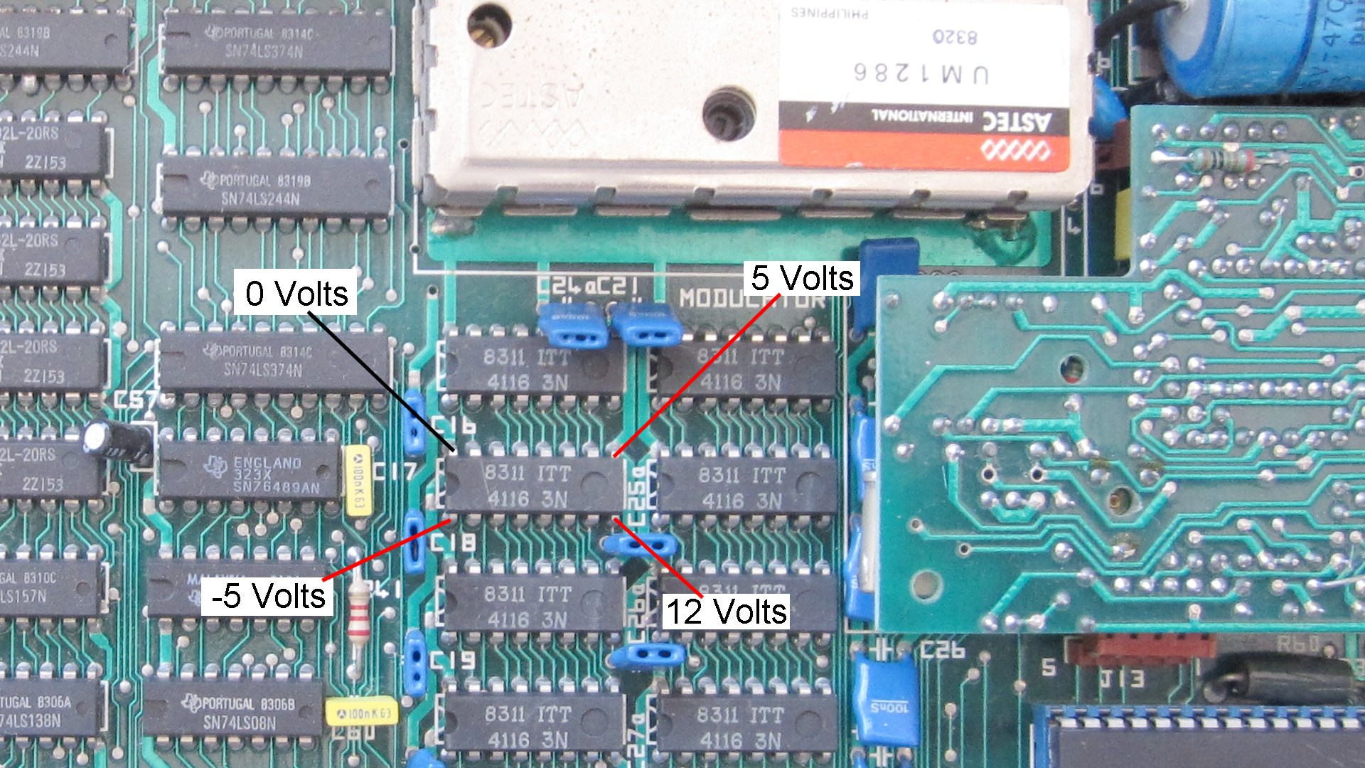
The 4116 DRAM chips are situated below the modulator?
Set the meter to 20v,
connect the black(-) probe to pin 16 (VSS, top left) 0V
connect the red(+) to,,
pin 9 (VCC, top right) test for 5V
pin 8 (VDD, bottom right) test for 12V
pin 1 (VBB, bottom left) test for -5V
Steve..
Re: No picture.
Posted: 29 Jul 2020 12:26
by Dave
That’s correct, and your positions reflect the chip orientationsin the MTX.
In general though, it’s better just to refer to just the PIN numbers. The dimple in the top of the chip (at the left in your convention) indicates the “top” of the chip (sometimes you’ll see a mark or indentation adjacent to pin 1).
From there, pins are numbered downwards on the left hand side, starting at 1. In this case, as you’ve said, pin 8 would be at the bottom. Then numbering continues from the next pin going counterclockwise, I.e., pin 9 is the pin on the opposite side. Numbering continues up that side until you reach the top, I.e, pin 16 for a 16 pin DIP, pin 14 for a 14 pin, pin 40 for a 40 pin etc.
Re: No picture.
Posted: 29 Jul 2020 12:48
by Steven.G
These?
- Image1.jpg (458.4 KiB) Viewed 6439 times
Re: No picture.
Posted: 29 Jul 2020 13:05
by Dave
Those