With the electrolytics capacitors changed, when I turn on the machine I get no output from the composite port. From the modulator I don't get a proper picture but I do get a blank screen. There's no sound and you can see the fast blow fuse flexing as soon as you turn on the power, leave it for any length of time and it breaks.
Any suggestions what might be causing the fuse to blow, a short somewhere, and how to test for it?
Charlie
Help with repair


Re: Help with repair
Hi Charlie,
It only started popping the fuse after you'd changed the capacitors?
A couple of obvious questions . . .
I take it that you removed the board from the case, rather than trying to replace them in situ?
Have you taken the board out again and looked closely at the areas on both sides of the board where you were working?
Check that there is no solder "splashes" on any adjacent tracks, or indeed any others close to where you were working.
regards
Dave
Re: Help with repair
Hi Dave,
Thanks for your reply, sorry for the confusion, the fuse was blown when I received the machine.
I did remove the board completely, I don't think I've caused any shorts. Is a short the likely culprit with the fuse doing that?
Charlie
Thanks for your reply, sorry for the confusion, the fuse was blown when I received the machine.
I did remove the board completely, I don't think I've caused any shorts. Is a short the likely culprit with the fuse doing that?
Charlie
Re: Help with repair
This area doesn't look very clever.


Re: Help with repair
I've gone over both sides of the board with a magnifying glass and there's loads of dodgy soldering all over the place, lots of burnt flux and signs of attempted repair.
Charlie
Charlie
Re: Help with repair
A short of some description is the obvious problem, but where to find it . . . . . .
I think it could be caused by any number of faulty components, but your photo of ZD2 does not look very healthy.
ZD2 is a 5.6V Zener, if it has failed short circuit, it would be taking the output of the TIP2955 straight to earth which would certainly blow the fuse.
Given how it looks, that might be the first place to start looking,
regards
Dave

Re: Help with repair
Okay, first a warning. The zener diode (ZD2) that is being talked about is designed to reduce the risk of damage to the chips if the +5V line suffers from an over-voltage problem. If that happens, it will go short circuit and the +5V rail will drop to around +1V.
So with your meter on voltage, see what voltage you get across it. Do not leave the machine powered up for more than 60 seconds at a time.
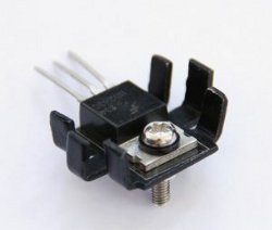
Second, check that the insulating kit for the power transistor Q4 (TIP2955) has both the mica "washer" (large rectangular clear flat plastic) and the black/brown small washer fitted. Check that they are not damaged. Use a meter on resistance (with the computer powered down) to confirm that the centre leg (which is connected to the tab of the transistor) is not in contact with the metal heat sink.
If the zener diode (ZD2) is still suspected, desolder one leg and lift it clear. A resistance check should confirm if it is short circuit (or not).
If you are still having problems, post and let us know, then I will try to help with the next step.
Mark
So with your meter on voltage, see what voltage you get across it. Do not leave the machine powered up for more than 60 seconds at a time.
Second, check that the insulating kit for the power transistor Q4 (TIP2955) has both the mica "washer" (large rectangular clear flat plastic) and the black/brown small washer fitted. Check that they are not damaged. Use a meter on resistance (with the computer powered down) to confirm that the centre leg (which is connected to the tab of the transistor) is not in contact with the metal heat sink.
If the zener diode (ZD2) is still suspected, desolder one leg and lift it clear. A resistance check should confirm if it is short circuit (or not).
If you are still having problems, post and let us know, then I will try to help with the next step.
Mark
“There are four lights!”
Step up to red alert. Sir, are you absolutely sure? It does mean changing the bulb
Autumn is here. Bye bye summer 2024...
Not as many MTXs as Dave!
Re: Help with repair
Thanks again chaps, with the meter on the diode I'm getting 0.45-0.5v. I'm powering down after 10 seconds or so as the board starts to smell hot.
My TIP2955 doesn't look anything like the one you pictured, there is no heatsink although these is some soldering iron damage. Here's a picture:-
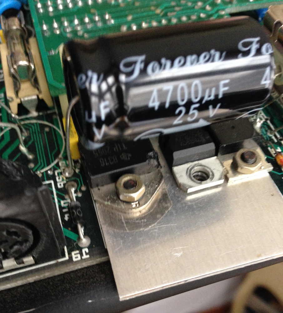
My TIP2955 doesn't look anything like the one you pictured, there is no heatsink although these is some soldering iron damage. Here's a picture:-
Re: Help with repair
The picture I posted was only meant to show the insulated "washers" (not many suitable pictures thrown up by a quick search).
Mark
Mark
“There are four lights!”
Step up to red alert. Sir, are you absolutely sure? It does mean changing the bulb
Autumn is here. Bye bye summer 2024...
Not as many MTXs as Dave!