Page 2 of 17
Re: Building a replacement MTX PSU - Sneak Preview
Posted: 20 Sep 2014 01:51
by 1024MAK
Re: Building a replacement MTX PSU - Sneak Preview
Posted: 20 Sep 2014 14:33
by Dave
Interesting !
It looks like you're putting DC out?
regards
Dave
Re: Building a replacement MTX PSU
Posted: 21 Sep 2014 03:33
by 1024MAK
Outputs:
Two 7.5V AC feeds (for feeding to the diodes that in turn go to the +5V regulator and the -5V zener diode supply circuitry)
One +16V DC feed, for feeding to one of the diodes that in turn supplies the +12V regulator.
The +16V DC supply is generated by a
LM2577 based step up DC to DC converter, which in turn is supplied by two diodes and a 2200uF 16V smoothing capacitor, which gets it's supply from the two 7.5V AC feeds.
Because I am using a 50VA transformer with a 230V primary, the two 7.5V AC outputs actually produce a bit more than the specification suggests when used at my house (where the "230V" mains supply is at, or close to 240V).
Schematic will be made available, along with a parts list when I get around to it

Also when I demonstrated it at Memofest 2014, Claus asked me about the performance when operating at 230V. So as I have a mains isolating transformer with various tappings, I will see if I can set it up to give 220V and 230V outputs, I can then test my MTX PSU using these voltages.
Code: Select all
My replacement MTX power supply unit
Test and set-up of LM2577 based step up DC to DC converter:-
LM2577 based step up DC to DC converter
Test input 8.01V at 19.7mA. Output (no load) 16.015V

Unit constructed, test load data:-
DIN  Wire      Output        No load
Pin. Colour    Name          Voltage
 1.  Yellow.   +16V DC       16.025V DC, 6mV ripple (meter)
 2.  Green.    7.5VH AC       8.93V AC
 3.  Red.      0V
 4.  Black.    0V
 5.  White.    7.5VL AC       8.92V AC

Internal DC supply (feeds LM2577 module):- 11.45V DC, 33mV ripple (no load).

Unit constructed, test load data:-
DIN  Wire      Output      Lamp          Current  Voltage
Pin. Colour    Name
 1.  Yellow.   +16V DC     Two 24V 5W    360mA    15.785V DC, 28.2mV ripple (meter)
 2.  Green.    7.5VH AC    One 12V 21W   1.37A     8.15V AC
 3.  Red.      0V
 4.  Black.    0V
 5.  White.    7.5VL AC    One 12V 21W   1.38A     8.18V AC
Re: Building a replacement MTX PSU
Posted: 07 Oct 2014 14:08
by Crazyboss
Mark
I think more people could be interested, cause people always miss the power unit.
As mentioned at the Memofest 2014, I am interested to buy one.
I am sure more people will be interested, so you can start a production line

Around what price can you produce one of those?
Re: Building a replacement MTX PSU
Posted: 08 Oct 2014 16:04
by 1024MAK
All in good time
Timing and cost is directly proportional to how much use I get of a TARDIS, should one be made available

The prototype has a mains switch which glows red when on and a green "output on" LED. For the "production version", I am open to suggestions as to the colour of this LED.
How many people are interested in buying one?
If you are a "maybe", but are going to remain undecided until the cost is known, please say so.
Also, for those people who would prefer to build their own, I will post up the details once I have drawn the schematic in a eye friendly form
Mark
Re: Building a replacement MTX PSU
Posted: 08 Oct 2014 18:09
by Dave
mmm, what colour should the LED be . . .
Difficult question, maybe 1 led is too restrictive, maybe we should have 1 LED per output voltage?


Even better, 2 LEDs per output, that flash at a frequency proportional to the voltage
It could replace my Christmas tree lights then

OK -
interested in buying, depending on price
(If you want me to draw the schematic for you, send me your "drawings" and I'll KiCad them)
regards
Dave
Re: Building a replacement MTX PSU
Posted: 25 May 2015 21:16
by 1024MAK
Construction Details
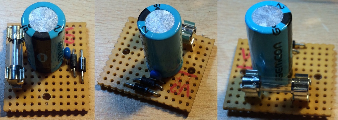
First, the DC board:
- DC board 1.jpg (216.42 KiB) Viewed 17659 times
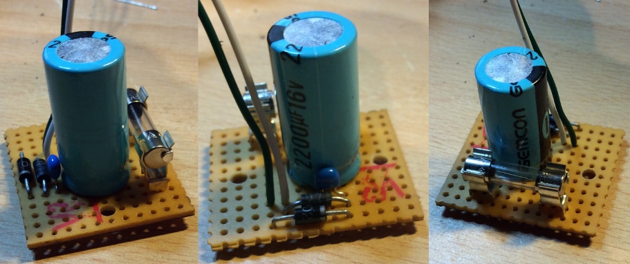
- DC board 2.jpg (149.08 KiB) Viewed 17659 times
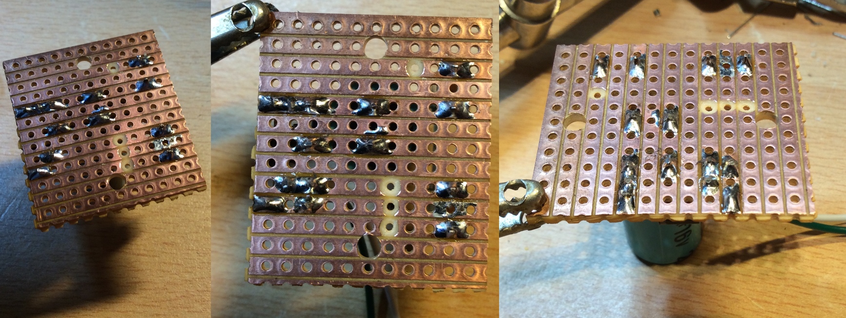
- DC board underside.jpg (582.78 KiB) Viewed 17659 times
Diodes:
Two 1N4001 or 1N4002 or a higher voltage rating.
Capacitors:
The small blue capacitor is a 100nF ceramic multilayer type, 5mm spacing.
The large capacitor is a 2200uF 16V electrolytic.
Fuse:
PCB fuse clips, 5mm pins, suitable for a 20mm type fuse.
1A anti-surge (A/S) / time delay (T) 20mm x 5mm glass fuse
More tomorrow (sorry it's slow, I'm a bit time poor...)
Mark
Re: Building a replacement MTX PSU
Posted: 26 May 2015 15:40
by 1024MAK
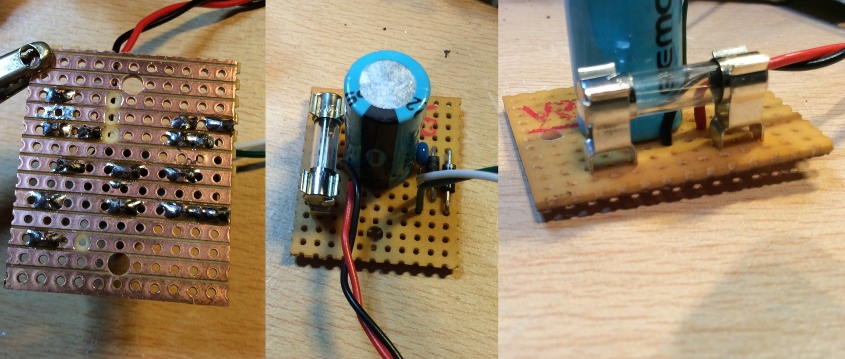
- DC board 3.jpg (157.87 KiB) Viewed 17654 times
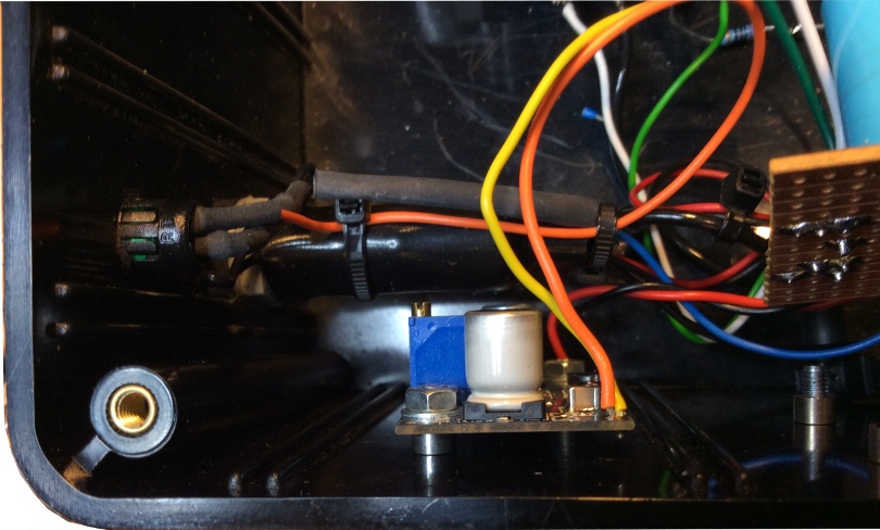
Step up DC to DC converter:
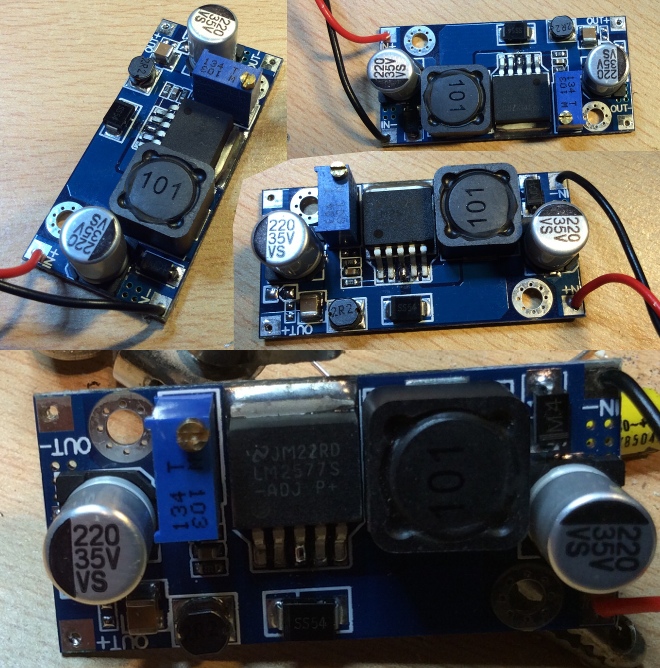
- Step up DC to DC converter.jpg (237.97 KiB) Viewed 17654 times
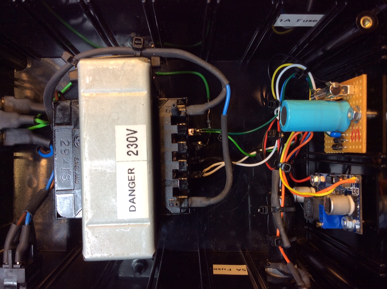
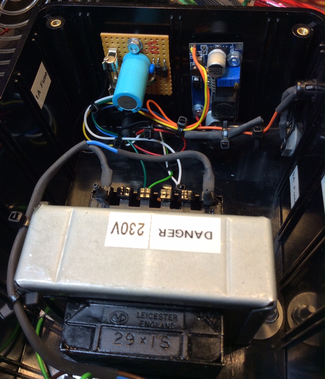
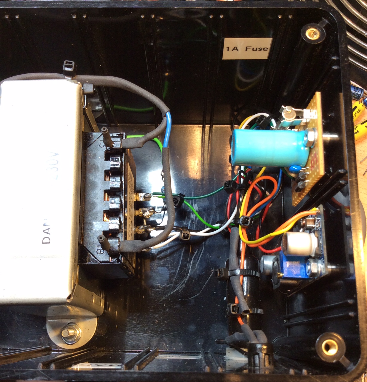
Inside:
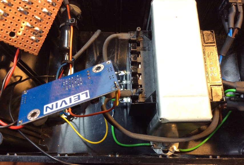
- Inside #01.jpg (227.42 KiB) Viewed 17654 times
Re: Building a replacement MTX PSU
Posted: 26 May 2015 15:43
by 1024MAK

- Inside #02.jpg (202.07 KiB) Viewed 17654 times
- Inside #03.jpg (155.21 KiB) Viewed 17654 times
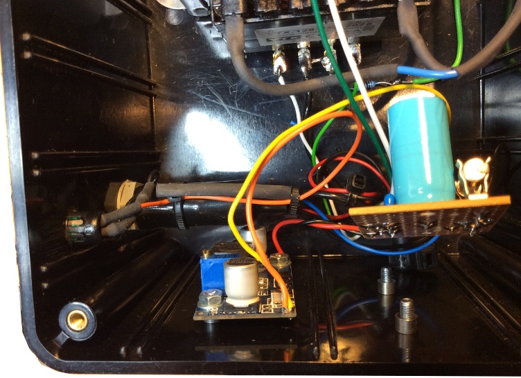
- Inside #04.jpg (198.62 KiB) Viewed 17654 times
Re: Building a replacement MTX PSU
Posted: 26 May 2015 15:48
by wyerd
Looking good Mark! Will you be posting circuit diagrams and a parts list as I'd like to make a 110v version?