Yep, that's what I thought but it's best to check. Thanks.
It doesn't matter what side of the fuse holder I use does it?
Building a replacement MTX PSU

Re: Building a replacement MTX PSU
Actually, comparing the schematic and the pictures I have posted, there is an inconsistency  . So can you hang fire please.
I'm at work right now. When I finish and get home I want to double check.
Mark
I'm at work right now. When I finish and get home I want to double check.
Mark
“There are four lights!”
Step up to red alert. Sir, are you absolutely sure? It does mean changing the bulb
Autumn is here. Bye bye summer 2024...
Not as many MTXs as Dave!
Re: Building a replacement MTX PSU
Sure - no problem.
You're working late.
You're working late.
Re: Building a replacement MTX PSU
The company where I work requires 24 hour cover, so I have to do nights every cycle.
Mark
Mark
“There are four lights!”
Step up to red alert. Sir, are you absolutely sure? It does mean changing the bulb
Autumn is here. Bye bye summer 2024...
Not as many MTXs as Dave!
Re: Building a replacement MTX PSU
Mark,1024MAK wrote:Actually, comparing the schematic and the pictures I have posted, there is an inconsistency
I'm at work right now. When I finish and get home I want to double check.
Mark
Have you had a chance to check?
Re: Building a replacement MTX PSU
Hi, panic over 
Last night, I was going to put a link up to a picture that I posted earlier in the thread. But when I looked at it on a iPad I could only see three wires , and this does not tie in with the schematic that I posted
However, after physically checking the wiring of the prototype PSU, I can confirm that the schematic is correct, it is just that the photo is very misleading.
This photo:
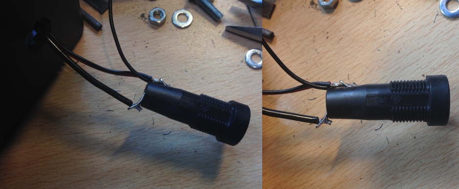
The terminal on the top of the fuse-holder (as viewed in the photo) actually has three black wires and one red wire connected to it. As you can see from the photo, at first glance, it looks like only two black wires. If you look a little closer, the red wire is hiding behind one of the black wires...
So one black wire and one red wire go to the DIN plug, one black wire is going to the resistor (for the LED). The remaining black wire goes to the strip-board.
The terminal on the bottom of the fuse-holder, is the high current wire from the transformer secondary windings.
And as I was about to say last night, for fuse-holders used in low voltage circuits, it does not matter which way round you connect the wires.
If it is easier for you, the black wire going to the resistor (for the LED) can be connected to the 0V track on the strip board instead, leaving just three wires to connect to the "output" fuse-holder terminal. Once you have stripped the ends of the insulation off, gently twist all the four(three) wires together. These are low current (thin) wires and the fuse-holder is rated at 6.3A (or 10A) so it should not be a problem getting the wires through the terminal hole and nicely connected.
Mark
Last night, I was going to put a link up to a picture that I posted earlier in the thread. But when I looked at it on a iPad I could only see three wires
However, after physically checking the wiring of the prototype PSU, I can confirm that the schematic is correct, it is just that the photo is very misleading
This photo:
The terminal on the top of the fuse-holder (as viewed in the photo) actually has three black wires and one red wire connected to it. As you can see from the photo, at first glance, it looks like only two black wires. If you look a little closer, the red wire is hiding behind one of the black wires...
So one black wire and one red wire go to the DIN plug, one black wire is going to the resistor (for the LED). The remaining black wire goes to the strip-board.
The terminal on the bottom of the fuse-holder, is the high current wire from the transformer secondary windings.
And as I was about to say last night, for fuse-holders used in low voltage circuits, it does not matter which way round you connect the wires.
If it is easier for you, the black wire going to the resistor (for the LED) can be connected to the 0V track on the strip board instead, leaving just three wires to connect to the "output" fuse-holder terminal. Once you have stripped the ends of the insulation off, gently twist all the four(three) wires together. These are low current (thin) wires and the fuse-holder is rated at 6.3A (or 10A) so it should not be a problem getting the wires through the terminal hole and nicely connected.
Mark
“There are four lights!”
Step up to red alert. Sir, are you absolutely sure? It does mean changing the bulb
Autumn is here. Bye bye summer 2024...
Not as many MTXs as Dave!
Re: Building a replacement MTX PSU
Here is a image adjusted (I've slightly boosted the red in the image) close-up:
Mind, on my iPad, the red wire still looks black 
Mark
- 5A fuseholder2.JPG (183.03 KiB) Viewed 12541 times
Mark
Last edited by 1024MAK on 02 Jul 2015 19:27, edited 1 time in total.
“There are four lights!”
Step up to red alert. Sir, are you absolutely sure? It does mean changing the bulb
Autumn is here. Bye bye summer 2024...
Not as many MTXs as Dave!
Re: Building a replacement MTX PSU
“There are four lights!”
Step up to red alert. Sir, are you absolutely sure? It does mean changing the bulb
Autumn is here. Bye bye summer 2024...
Not as many MTXs as Dave!
Re: Building a replacement MTX PSU
Great - thanks for the info.
Getting there!

Getting there!
Re: Building a replacement MTX PSU
Coming along nicely 

Mark
Mark
“There are four lights!”
Step up to red alert. Sir, are you absolutely sure? It does mean changing the bulb
Autumn is here. Bye bye summer 2024...
Not as many MTXs as Dave!