- Screenshot from 2021-02-01 14-58-45.png (75.33 KiB) Viewed 27959 times
My Z180 running CP/M

The boot process is slightly complicated.
Although Rememoriser and CFX both support multiple CP/M drives on a single media, they don't use partitions in the now usual PC (DOS, Windows or Linux) sense. Instead they just store the drive images in successive 8MB slices at the bottom of the media. This renders the media unusable for any other purposes unless it is reformatted.
My Z180 storage is using Micro SD cards. The minimum size of these readily available now is 8GB or 16GB. To use that amount of storage to just store four CP/M drive images (32MB) seemed to be a waste. I therefore partitioned the SD card in the modern PC sense. I created two partitions:
- A 32MB partition of type 0x52. This partition type is documented as being for CP/M. This is used to hold four 8MB CP/M drive images.
- The remainder of the space as a FAT32 partition. This can be used as normal from a PC to store any relevant files such as my Python assembler and any Z80 source.
Next I had to create a CP/M system image. To start I dumped the system tracks from a Memotech disk, and disassembled it, assisted by an existing CP/M disassembly published on the net. After a bit of work, this gave me a source code that I could re-assemble to duplicate the Memotech system image. The system image consists of four parts:
- System bootstrap loader - 0.25 KB
- CCP - Console command processor - 2.00 KB
- BDOS - Basic Disk Operating System - 3.50 KB
- BIOS - Basic Input Output System
The Memotech regards CP/M disks as having 26 sectors (128 bytes each) per track and the complete system image resides in the first two tracks. This gives 7.50 KB of space for the system image. The CPP and BDOS are fixed leaving only 2.00 KB for the loader and BIOS.
This is not much space for a complete BIOS, and the Memotech does not have one in the system image. Instead it relies upon routines previously loaded into high memory by the CP/M boot ROM. Interestingly, the same is true of the Digital Research example BIOS code which makes use of calls into existing Monitor code.
For me, for ease of development, I wanted to have most or all of the BIOS on the SD card, and this space was proving tight, particularly when I had to include code to debug a few issues with my CCP and BDOS port. I could have changed the format of the disk images, either using 32 sectors per track (which would have made some of the calculations easier), or using 3 tracks for the system image. But either of those changes would have meant I had to build new disk images from scratch rather than being able to simply copy ones from CFX.
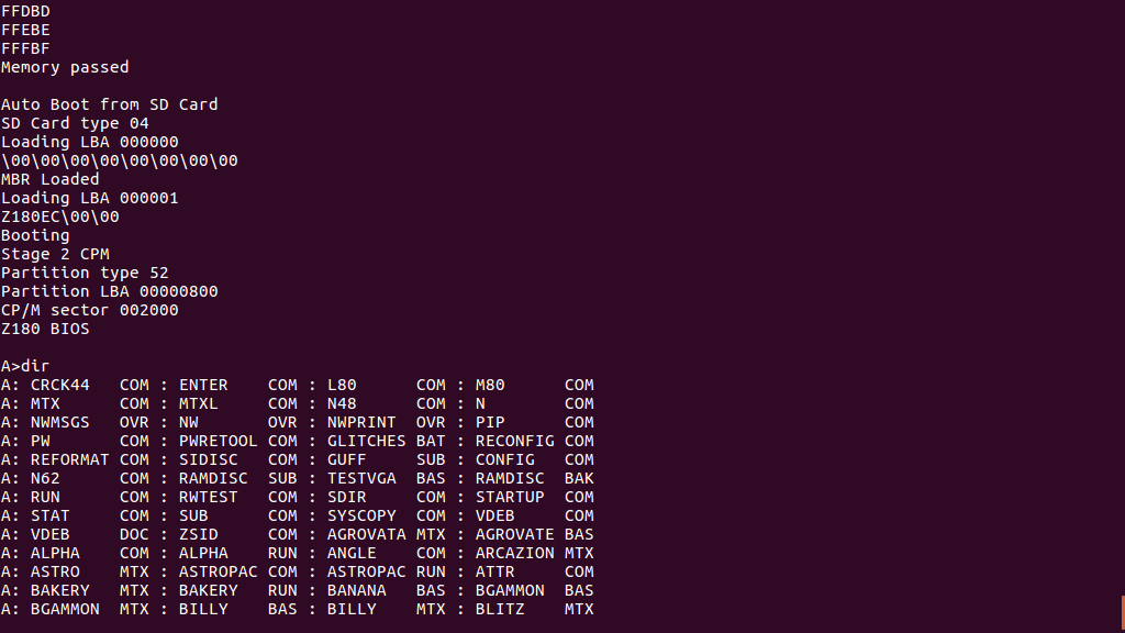
As mentioned, I have partitioned the SD card. This means that the partition table is at LBA 0. However, the first partition does not start at LBA 1. Instead it starts at LBA 0x800 (=2048). Therefore there is nearly 1MB of free space between the partition table and the start of the first partition. In the PC world this would typically be used for boot loader code. I can therefore use it for similar purposes.
I have therefore decided that my Z180 code on SD card will start with the signature bytes "Z180EC". My ROM bootloader then works as follows:
- Load LBA 0 into memory. Check for the "Z180EC" signature, and if so jump into the code. This for media which has not been partitioned.
- Test for a valid partition table (last two bytes 0x55, 0xAA). If not declares the SD card not bootable.
- Loads LBA 1 into memory. Check for the "Z180EC" signature, and if so jump into the code. This for system images that will not fit in the SP/M drive image system tracks.
- Scans through the partition table, looking for partitions of type 0x52 (CP/M) or 0x7F (Experimental). If found, load the first block of the partition into memory. Check for the "Z180EC" signature, and if so jump into the code.
- Declare the SD card not bootable.
In the screen shot (top) the system has been booted from LBA 1. This second stage loader still has to scan the partition table to find the location of the CP/M drive images.
I have still to fit the RTC and FPU to my second board. However the main thing that prevents my Z180 system being stand-alone is that I am using a serial port for input, so I have to connect my laptop as a terminal. I did include connections which in theory should allow me to connect a keyboard to the display Propeller chip, however I don't think the chip has enough capacity to run both display and keyboard processing, certainly not USB.
Anyway, serial input is the most logical way to get key presses into the Z180. So my next move is probably to add a keyboard to serial board. I could use another Propeller or even an RPi Pico, which would support USB. But either of these seem excessive, so I will see whether I can do PS/2 to serial using a low end PIC chip.
