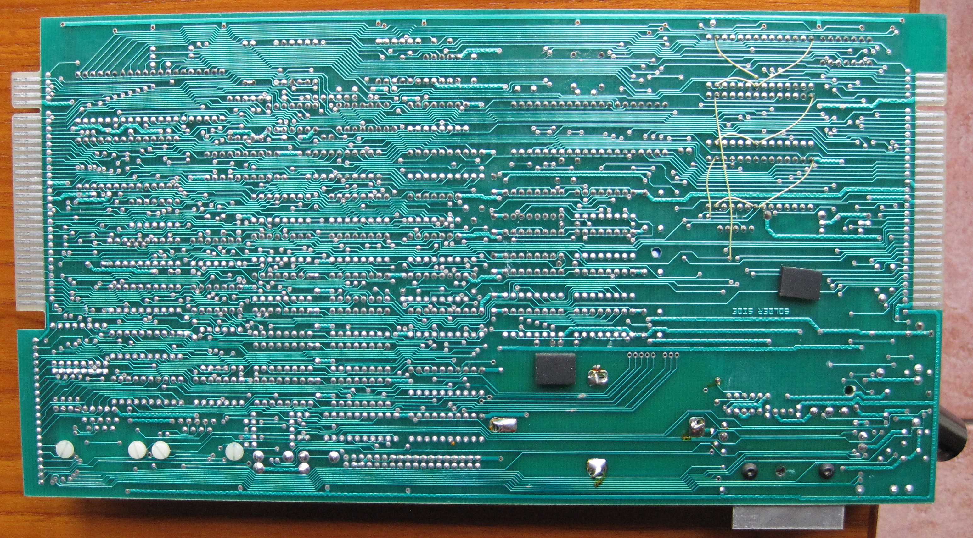
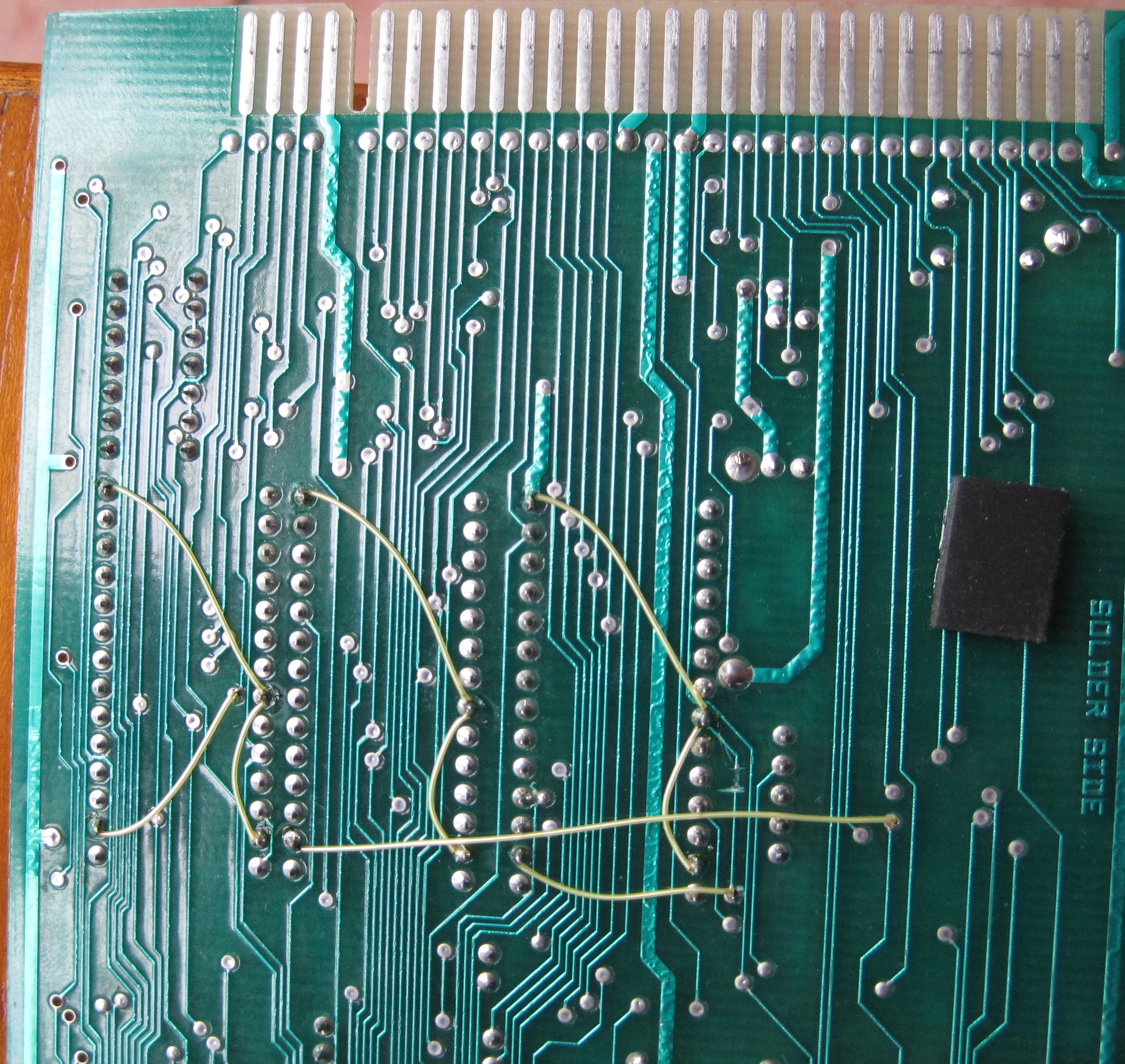
As information on Mask ROM and PROM chips is hard to find, and as there are a number of different pin-outs for different EPROM chips, I thought I would provide some of the much needed information.
I have attached a zip file containing spreadsheet files (in OpenOffice.org and Excel file types) that compares the different pin-outs of the different chips (both some Mask ROM, some PROM and some EPROM types).
There are three different files. One for 4000-04 boards, one for 4000-05 boards (as these normally use different chips) and a general one. The zip file is called "ROM & EPROM pin-outs.zip"
Code: Select all
Issue 4000-05
=============

Uses three 8k byte Mask ROM chips ("A", "B" and "C").
On the board, they are "hard-wired" as position 'a' of links 1,2,4 and 5 as shown on the schematic diagram.
ROM "C" (position 10H on the board), pin 22 is from the extra 74LS00 (10J).
ROM "B", pin 22 is from the extra 74LS00 (10J).

Issue 4000-04
=============
Uses two ROMs or two EPROMs (one 8k byte and one 16k byte)
See pin-out diagram.Code: Select all
ROM "A" (position 9H)
Pin 2  Link 5 a  to 0V
            5 b  to A13
            5 c  to A12 (production board setting)

Pin 20 Link 4 ab to A11
            4 c  to /RD (production board setting)

Pin 22 --------- to /CEA  (individual ROM select)

Pin 23 Link 2 ab to A12
            2 c  to A11 (production board setting)

Pin 26 Link 1 ab to +5V
            1 c  to A13 (production board setting)

Pin 27 Link 13 H to +5V (production board setting)
            13 L to 0V

ROM "B" (position 8H)
As for ROM "A" except:
Pin 22 --------- to /CE64B (individual ROM select)Mark
Edited on 2014-10-14 to add some extra information.


