I've chopped up a bit of scrap matrix board and added a 32 pin and 20 pin socket plus some jumpers.
to come up with this mock up:
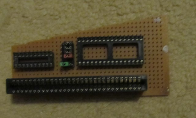
- rom board idea.jpg (33.73 KiB) Viewed 14758 times
A 20 pin 16V8 GAL or CPLD has more than enough capacity to allow for paging in 4 different rom Images from a 32k, 28 pin EPROM or EEPROM.
However EPROMS are a pain for development because of the erase time. Electrically erasable memory is easier to work with, and it turned out only 1 pin has to change function when fitting a 32pin socket to use a 64K EEPROM like a 27E512 or a 128K flash like the 39SF010 as well as a 27C256.
Since the larger capacity device is going to be fitted at least for development, I decided to add some extra options. So the board has 5 jumpers.
One jumper deals with the pin that changes function. On 32k EPROMs where it's the program enable pin that needs to be pulled high and the larger capacity chips where it's an address line and needs to connect to the paging logic.
One jumper decides whether the diagnostic rom images are available to be paged in, or if the normal ones are.
The other 3 decide exactly what rom images are active.
With the normal roms setting It would be one jumper for each of the roms A B and C to individually selected to replace the on-board ones.
With the diagnostic rom setting the extra space on the larger devices can be used to test the rom paging system from within the diagnostics. Test with WINcupl suggest switching the 16 ROM images that would fit in a 128k FLASH chip is doable without needing to move to a larger GAL/CPLD.
Hopefully I'll get some time over the weekend to put some wires onto the mock up and see what happens when its connected to a real MTX!

